- Posts: 116
- Thank you received: 73
KZ700 analog fuel level indicator
- KeylAmi!
-
 Topic Author
- Offline
- User
-

Registered
- Engineer with ADHD
Less
More
18 May 2026 17:12 #924049
by KeylAmi!
Current project:
'84 KZ700
KZ700 analog fuel level indicator was created by KeylAmi!
So my KZ has an analog meter for fuel level. I rewound the fuel level sensor that goes in the tank. But it wasn’t an *exact* match for the original. So… I can get either the empty OR the fuel point to be accurate. Not both.
The meter works by heating a bimetallic strip to actuate the needle on a spindle. As the strip heats, it flexes the needle from empty to full. Which matches with the sensor decreasing resistance as it approaches full. Lower ohms = higher current. Higher current = more heat.
I discovered that the meter has a convenient adjustment mechanism. I didn’t get pictures when I had it apart. I will try to remember later this week.
If you have one, with the meter face installed, but the outer cover removed, look at the lower left edge of the stamped/formed sheet metal framing underneath. There will be an 8 shape. With toothed regions corresponding to the top and bottom edge of the 8 shape. Using a small flat head screwdriver, you can rotate the inner mechanism by gently twisting against these teeth. It rotates the whole bimetallic spring and supporting frame, in relation to the needle sweep range. Essentially, muting or magnifying the movement of the spring.
hope this helps someone!
Current project:
'84 KZ700
The following user(s) said Thank You: slmjim+Z1BEBE, Wookie58
Please Log in or Create an account to join the conversation.
- Wookie58
-

- Offline
- Moderator
-

Registered
Less
More
- Posts: 6415
- Thank you received: 4060
19 May 2026 03:31 #924060
by Wookie58
Replied by Wookie58 on topic KZ700 analog fuel level indicator
Just out of interest, with this type of meter does the reading fluctuate wildly with "fuel slosh" as reported by Warren on his "J" or is the response time of the needle less "immediate" ?
Please Log in or Create an account to join the conversation.
- KeylAmi!
-
Topic Author
- Offline
- User
-
Registered
- Engineer with ADHD
Less
More
- Posts: 116
- Thank you received: 73
19 May 2026 03:33 #924061
by KeylAmi!
Current project:
'84 KZ700
Replied by KeylAmi! on topic KZ700 analog fuel level indicator
Fuel slosh doesn’t exist with this type at all. The time for needle to sweep from full to below empty when turning the ignition off is measured in seconds.
Current project:
'84 KZ700
The following user(s) said Thank You: Wookie58
Please Log in or Create an account to join the conversation.
- KeylAmi!
-
Topic Author
- Offline
- User
-
Registered
- Engineer with ADHD
Less
More
- Posts: 116
- Thank you received: 73
19 May 2026 06:08 #924066
by KeylAmi!
Current project:
'84 KZ700
Replied by KeylAmi! on topic KZ700 analog fuel level indicator
Wookie,
Did some ebay digging. There are at least two part numbers for this type, that use the same mechanism.
28011-1027 : KZ1000
28011-1032 : KZ700
In the image (KZ1000 variant) I've attached, i've marked some points of interest in red.
arrow, lower right: rivet acting as a hinge for the adjustment mechanism
vertical line, top center: the pin at the end of the spring that sweeps the needle
arrow, top center: FRAGILE wire winding over portion of the bimetallic strip. The strip is the two bars in the middle. the arrow is over one of the bars.
circle, center: this is the adjustment point I am referring to. It essentially changes the distance between the moving pin and the needle spindle.
adjusting this point "clockwise" when viewed from the gauge face, will make the pin closer to the needle. So bimetal strip flex = large needle swing.
adjusting counterclockwise moves this pin further from the needle spindle. This makes the needle swing less, for the same amount of flex.
Extremely simple design. And added bonus of built in buffer for fuel slosh. One downside though, full tank = high current. A couple of amps.
I do not know just how much sender ohm variation can be adjusted for.
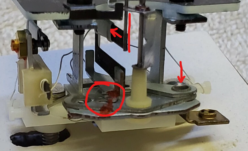
Of note: there is another heater/bimetal strip, on the left. same circuit. My best guess is that this is an "over-temp safety". So if the current is high enough and too big of a "swing" is being attempted, this breaks the circuit until it cools back down. At full, with the fuel level sender around 5 ohms, that'd be 2-3 amps. but at empty, it will be at or less than 1/10 of an amp. There is adjustment for this portion too. That nut and threaded portion controls just how far the over-temp strip has to flex before the circuit is broken. Ideally, I imagine this is just a "whiff" above current flowing at "FULL".
Did some ebay digging. There are at least two part numbers for this type, that use the same mechanism.
28011-1027 : KZ1000
28011-1032 : KZ700
In the image (KZ1000 variant) I've attached, i've marked some points of interest in red.
arrow, lower right: rivet acting as a hinge for the adjustment mechanism
vertical line, top center: the pin at the end of the spring that sweeps the needle
arrow, top center: FRAGILE wire winding over portion of the bimetallic strip. The strip is the two bars in the middle. the arrow is over one of the bars.
circle, center: this is the adjustment point I am referring to. It essentially changes the distance between the moving pin and the needle spindle.
adjusting this point "clockwise" when viewed from the gauge face, will make the pin closer to the needle. So bimetal strip flex = large needle swing.
adjusting counterclockwise moves this pin further from the needle spindle. This makes the needle swing less, for the same amount of flex.
Extremely simple design. And added bonus of built in buffer for fuel slosh. One downside though, full tank = high current. A couple of amps.
I do not know just how much sender ohm variation can be adjusted for.
Of note: there is another heater/bimetal strip, on the left. same circuit. My best guess is that this is an "over-temp safety". So if the current is high enough and too big of a "swing" is being attempted, this breaks the circuit until it cools back down. At full, with the fuel level sender around 5 ohms, that'd be 2-3 amps. but at empty, it will be at or less than 1/10 of an amp. There is adjustment for this portion too. That nut and threaded portion controls just how far the over-temp strip has to flex before the circuit is broken. Ideally, I imagine this is just a "whiff" above current flowing at "FULL".
Current project:
'84 KZ700
The following user(s) said Thank You: Wookie58
Please Log in or Create an account to join the conversation.
- Warren3200gt
-

- Offline
- User
-
Registered
Less
More
- Posts: 1745
- Thank you received: 924
19 May 2026 11:15 - 19 May 2026 11:38 #924074
by Warren3200gt
Replied by Warren3200gt on topic KZ700 analog fuel level indicator
AI suggests this for my bouncy needle issue. Kinda makes sense to my limited electrickery ability,
what do you guy (s),(intentional name drop 🤣) think?
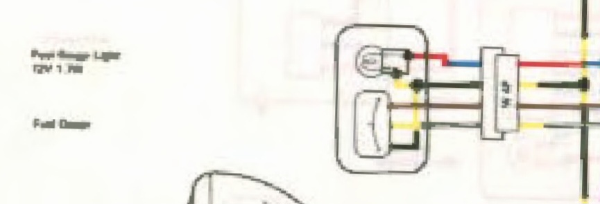
Capacitor Damping: A simple DIY damper circuit often involves placing a large capacitor (such as 100 u F) to (1000 u F) across the gauge’s sender terminal and ground. The capacitor absorbs these rapid electrical fluctuations and discharges them slowly, creating an averaged, steady reading.
So across the brown and any earth should work. Right?
what do you guy (s),(intentional name drop 🤣) think?
Capacitor Damping: A simple DIY damper circuit often involves placing a large capacitor (such as 100 u F) to (1000 u F) across the gauge’s sender terminal and ground. The capacitor absorbs these rapid electrical fluctuations and discharges them slowly, creating an averaged, steady reading.
So across the brown and any earth should work. Right?
Last edit: 19 May 2026 11:38 by Warren3200gt.
Please Log in or Create an account to join the conversation.
- KeylAmi!
-
Topic Author
- Offline
- User
-
Registered
- Engineer with ADHD
Less
More
- Posts: 116
- Thank you received: 73
19 May 2026 11:38 #924075
by KeylAmi!
Current project:
'84 KZ700
Replied by KeylAmi! on topic KZ700 analog fuel level indicator
what style of movement do you have? the one that looks kinda like a motor?
without knowing the details of the system, i have concerns.
The type of capacitor makes a difference.
For the needle bounce, are we talking frequent sweeps, or more like those "dumb gages" that are a float over a twisted shaft in a riding mower?
While yes, a capacitor smooths out *voltage* noise, it's not going to do much for current. depends on how the gage is designed to function. Seeing the signal that is causing your needle to bounce would be very helpful.
Current project:
'84 KZ700
Please Log in or Create an account to join the conversation.
- Warren3200gt
-
- Offline
- User
-
Registered
Less
More
- Posts: 1745
- Thank you received: 924
19 May 2026 11:40 - 19 May 2026 11:45 #924076
by Warren3200gt
Replied by Warren3200gt on topic KZ700 analog fuel level indicator
Variable (arm sweep) resistor.
like a potentiometer.
100ohm resistance guage shows empty. Oohm resistance guage shows full.
doesnt say it on the ai example but it would need to be an electrolytic capacitor.
like a potentiometer.
100ohm resistance guage shows empty. Oohm resistance guage shows full.
doesnt say it on the ai example but it would need to be an electrolytic capacitor.
Last edit: 19 May 2026 11:45 by Warren3200gt.
Please Log in or Create an account to join the conversation.
- Wookie58
-
- Offline
- Moderator
-
Registered
Less
More
- Posts: 6415
- Thank you received: 4060
19 May 2026 12:35 #924077
by Wookie58
Replied by Wookie58 on topic KZ700 analog fuel level indicator
Hopefully my build should be finished by the end of June ish so I will have a play with the “K” one I have then
The following user(s) said Thank You: Warren3200gt
Please Log in or Create an account to join the conversation.
- KeylAmi!
-
Topic Author
- Offline
- User
-
Registered
- Engineer with ADHD
Less
More
- Posts: 116
- Thank you received: 73
19 May 2026 15:31 #924079
by KeylAmi!
Current project:
'84 KZ700
Replied by KeylAmi! on topic KZ700 analog fuel level indicator
HUGE, EXTREME, PAY ATTENTION WARNING:
Do not attempt to check the meter without the float unit windings submerged in fuel. It’s keeping the windings cool.
If you apply full voltage to the windings in open air, they will promptly “let the magic smoke out”
Do not attempt to check the meter without the float unit windings submerged in fuel. It’s keeping the windings cool.
If you apply full voltage to the windings in open air, they will promptly “let the magic smoke out”
Current project:
'84 KZ700
The following user(s) said Thank You: Wookie58
Please Log in or Create an account to join the conversation.
Moderators: Street Fighter LTD