Porting the Z1, KZ900, KZ1000 and ZX1100A
by Joe Hooper
(2-1-2026)
I am writing this to pass on some information on porting the Kawasaki Z1 and it’s derivatives that I have accumulated over the last fifty two years.
I will describe the procedure that I use for porting and the results obtained.
To start, I perform a valve job. I use Kwik Way stones and first I grind the 45 degree seat and take it down until the diameter is about .020” larger than the valve to be used. I then paint the seat with Dykem blue machinist dye. I then make the 30 degree cut until the measured diameter on the 45 degree part is about .005” - .010” smaller than the valve to be used. This is followed by the 60 degree cut to reduce the width of the seat to about .020” - .025”. What I end up with is a sharp blue line that is where the seat is. I will use this as a guide when the porting begins. The above procedure is to get the sealing surface as far out as possible.
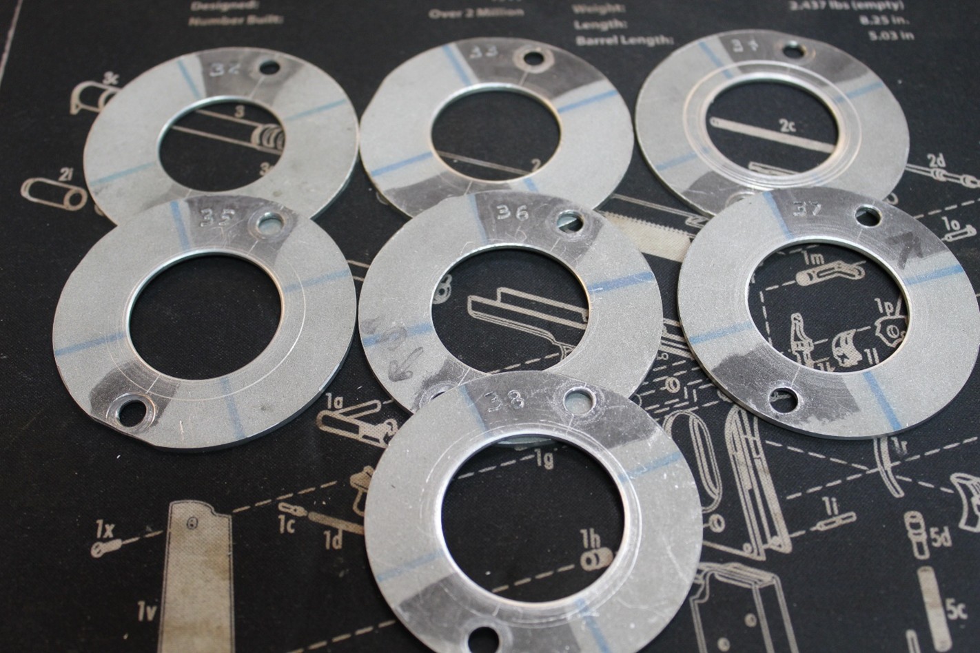
For the intake port, if the head is to be setup with larger than stock carburetors, I will paint the inlet surface with the Dykem dye. I will then use a template to scribe a sharp line to the size dictated by the carbs in use. I built templates in sizes 32, 33, 34, 35, 36, 37 and 38 millimeters. (pictured below)
For the exhaust port, I paint the exhaust gasket surface with the Dykem dye. I then use a stock exhaust gasket forcing it to the top of the port and scribe a sharp line. For oversized valve applications, I use an inverted cone carbide tipped burr ¼” shank with a ½” width on the large side of the cone to raise the exhaust gasket surface about .100” to .150”. After raising the top of gasket bore, I paint the dye and scribe the line.
This will give you all the markings you need on the head and you are ready to start porting.
Lets talk about tools for a moment. A quarter inch air powered die grinder is my tool of choice. I use an Ingersoll Rand with a swivel hose attachment, this helps to get your eyes behind the die grinder to see where you are grinding. The IR die grinder is very stout and does not vibrate when I use long bits at high speed. It is a little pricey. If you are just doing one head, you can get a $20 die grinder at Harbor Freight.
Do not try to use a Dremel tool. It is a toy and should only be used on toys.

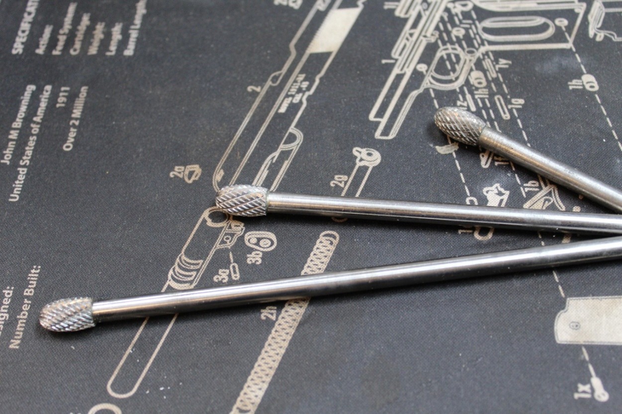
Other than the aforementioned reverse cone burr, there is only one shape of burr that is needed. It is the oval shape (D shape). There is nothing inside the port that can not be shaped with a 3/8” oval carbide head on a ¼” shank. I use them in 2”, 4” and 6” shank. I also use the diamond pattern on the carbide as it seems to resist clogging a little better than the straight flute. Pictured below.
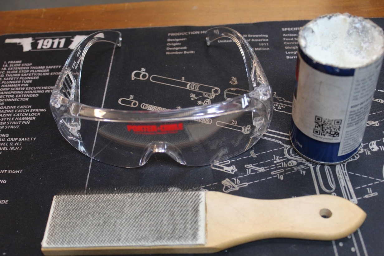
You will also need eye protection, a lubricant for the carbide burrs and a card file to clean the burrs when they become clogged with aluminum. Pictured below.
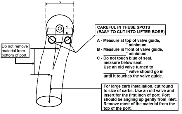
First we will discuss the intake port. I have pasted in a copy of what I have used for the last thirty years or so. It shows a couple of places that I determined to be important to the overall port shape. Measurement “A” is taken with a snap gauge resting on top of the valve guide. Measurement “B” is taken with the snap gauge touching the inlet side of the valve guide. Measurement “C” is taken just beneath the seat as described earlier. Measurement C is best taken using an old valve turned to the proper size. There is a table at the end of the porting instructions that gives the values for all of the measurements for three types of heads and several different combinations of porting stages.
Let me break down the porting stages that I use:
Stage 1 is how I would port the head if using stock sized valves and stock sized carburetors. If you look at the port drawing below, the porting work essentially ends at the runner leading to the valve guide. There is no reason to remove any material closer to the inlet as the port is already 28mm in this area and the carburetors are 28mm, with the exception of the KZ900 which utilizes 26mm carburetors. Stage 1 porting is good for an increase of 15%-20% flow.
Stage 2 is how I would port the head if using oversized valves and oversized carburetors. For the early style engines from 1973 to 1980 the stock sized intake valve is 36mm and the largest valve that can safely be installed on the stock seat is 37.5mm. That is the valve size that I have designed this for. For the later style 1981-2005 J-model head, the stock sized intake valve is 37mm and the largest valve that can safely be installed on the stock seat is 38.6mm. The measurements A, B and C are taken in the same spots. The inlet of the intake runner is opened up as round as possible to the same size as the carburetors to be used. Stage 2 porting is good for an increase of 25%-30% flow.
Stage 3 is how I would port the head if using oversized seats and the largest valves I can stuff in there along with the biggest carburetors available.
There is also a Stage 1½ which has two configurations. One would be stock sized valves and oversized carbs, In this case the measurements A, B and C would be the Stage 1 measurements and the intake inlet opened up to the carburetor size. The second type of Stage 1½ would be oversized valves and stock sized carburetors. In this case, the measurements A, B and C would be the Stage 2 sizes and the inlet of the port would be left untouched.
With these measurements in mind, you can do a good port job by keeping a few things in mind. First of all, try not to remove any material from the bottom of the port. Naturally, there are exceptions to this rule. If you look at the bottom of the intake port as it gets to the steel insert of the seat material, it will usually end up with a sharp point there. This needs to be smoothed as well as possible without extending back into the port very far. Additionally, if you are installing oversized carbs, you must start the port at the intake manifold and that is centered on the two bolt holes. So, you must remove material from the bottom of the port in order to make it round and the correct size. In that case, you should start slanting up with the bottom of the port almost immediately. On the top of the port, I make the valve guide runner into a triangle shape with concave sides. I also take out more off of the inside of the port, thus moving the runner a little bit to the outside of the port.
Note on the drawing that there are two places of particular concern as it is very easy to go too high and cut into the lifter bore.
Your objective should be to vary the cross sectional area of the port as little as possible for it’s entire length.
My porting and flow testing experience has shown me that the area that will produce the largest increase in flow is the first half inch of the port under the valve seat.
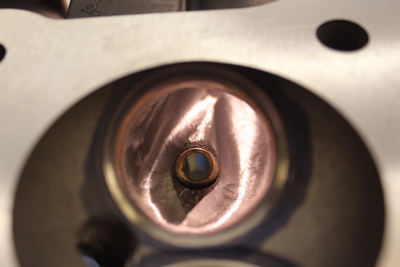
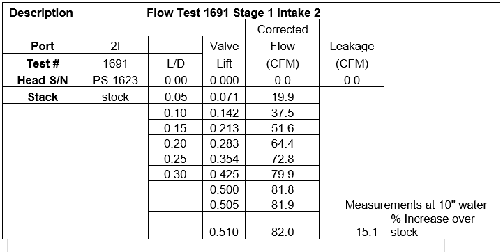
Below is a finished Stage 1 intake port. It had a 15.1% improvement in flow over a stock port.
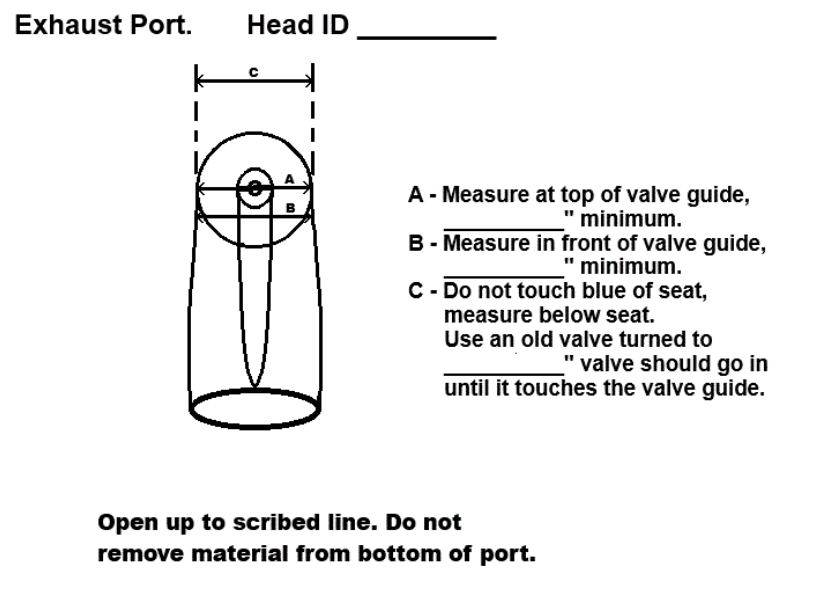
Next we will discuss the exhaust port. I have pasted in a copy of what I have used for the last thirty years or so. I am obviously not a graphic artist. It shows a couple of places that I determined to be important to the overall port shape. Measurement “A” is taken with a snap gauge resting on top of the valve guide. Measurement “B” is taken with the snap gauge touching the outlet side of the valve guide. Measurement “C” is taken just beneath the seat as described earlier. Measurement C is best taken using an old valve turned to the proper size. There is a table at the end of the porting instructions that gives the values for all of the measurements for three types of heads and several different combinations of porting stages.
The guidelines for the exhaust port are pretty much the same as the intake. That is try not to remove any material from the bottom of the port. Again if you look at the bottom of the exhaust port where the aluminum meets the steel insert of the seat material, it will usually end up with a sharp point there. This needs to be smoothed as well as possible without extending forward into the port very far. I like to shape the runner behind the valve guide into a point meeting in the middle at the end of the port. This serves two purposes. It helps to smooth the flow as it passes the valve guide and it helps to prevent cutting into the lifter bore.
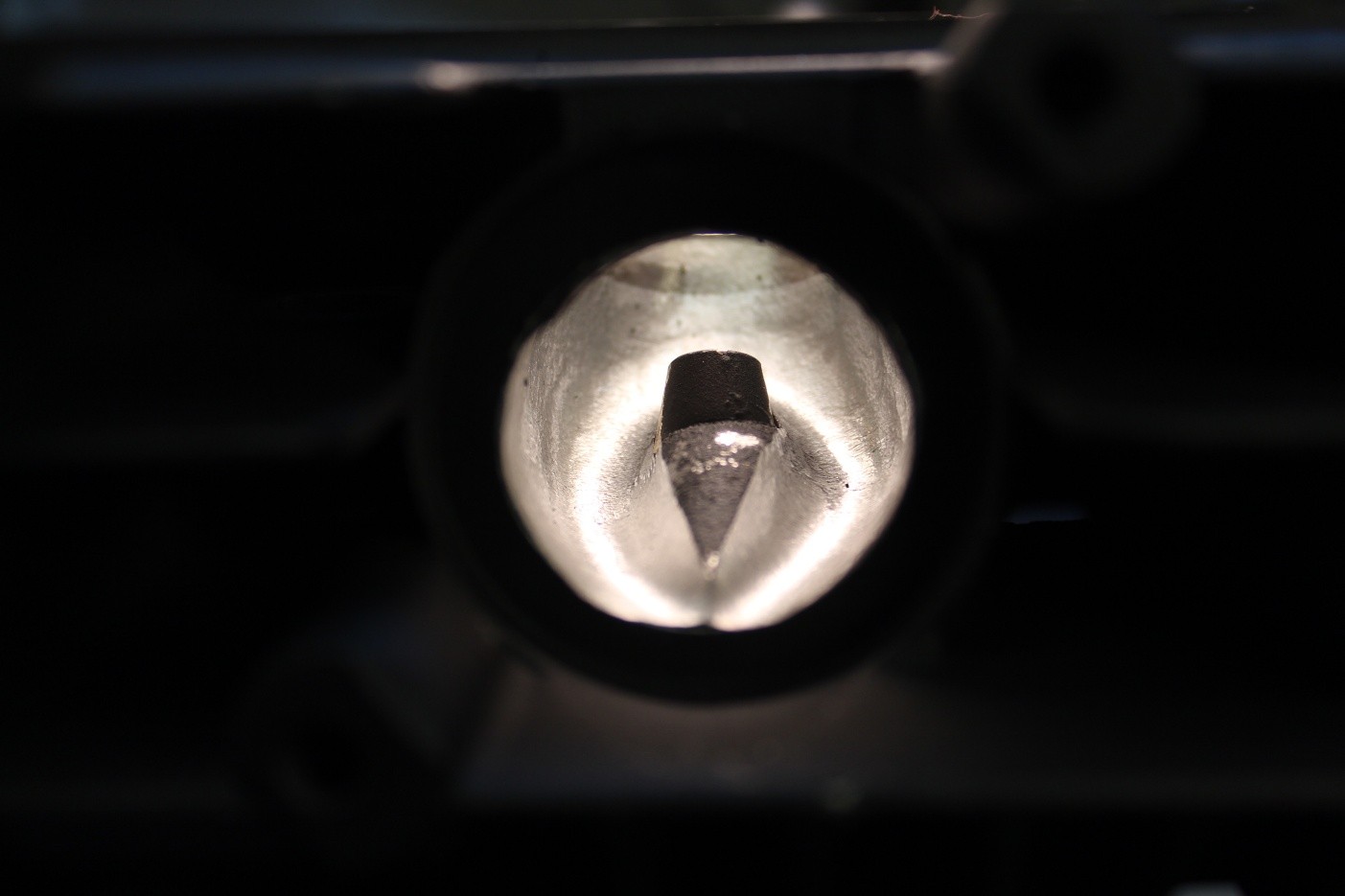
Below is a finished Stage 1 exhaust port. It had a 16.2% improvement in flow over a stock port. I am not a photographer and was concentrating on getting a clear shot of the interior of the port. Unfortunately you can not see what is left of the line scribed on the exhaust gasket surface and see how I stopped making the exit round at the bottom of the port.
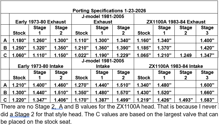
There are no Stage 2, A and B values for the ZX1100A head. That is because I never did a Stage 2 for that style head. The C values are based on the largest valve that can be placed on the stock seat.
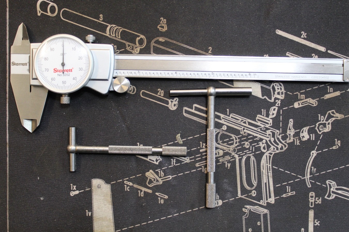
These are the measuring tools that I use. Snap gauges to measure inside the ports and a dial caliper to measure the snap gauge.
Below is a picture of my old reliable Superflow 110 flow bench.
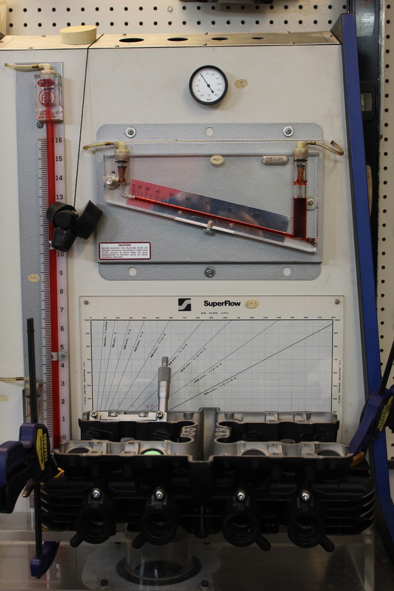
Below is a picture of a 1973 Z1 head mounted on the flow bench. It is setup for exhaust flow in this photo. You can see the micrometer mounted above the exhaust valve to allow it to be opened to any point in thousandths of an inch. This particular head is the same one who’s exhaust and intake ports were shown earlier. It is the head I was working on when I put this paper together.

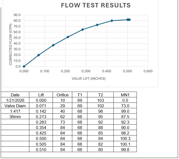
When I perform flow testing, I use increments of lift over diameter. I use them for .05 L/D up to .30 L/D in steps of .05. I then add a few check points above .30 L/D to cover higher lift of drag racing style camshafts. I set up a spread sheet to calculate the L/D check points for me. I enter the valve diameter and the program calculates my check points. The program is also set up to perform the calculations to adjust for inlet and outlet temperature.
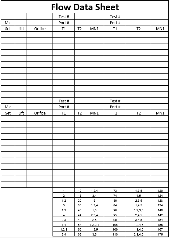
Below is a spread sheet for the 1973 Z1 head #2 intake port. Below that is the flow data sheet which lists all of the pertinent information recorded during the flow test. At the bottom is a table that lists the flow capabilities of all combinations of open test ports. Each of the five ports at the top of the flow bench has a maximum flow provided by Superflow. The manometer on the left is the test pressure and the manometer in the middle of the machine is the percentage of maximum flow. When performing a flow test, I adjust the valve opening to correspond to the first check point. I usually start at maximum lift and work my way down. I do it that way to try and control the temperature of the vacuum motors. I first adjust the suction manometer to 10” of water. It is also required at this point to adjust which orifices are open. I try to adjust the open orifices to keep the percentage manometer at 80% to 100% if possible. I then quickly record the percentage manometer followed by inlet temperature, outlet temperature and which orifices are open. The table at the bottom of the data sheet will give me the number to enter for orifice by providing the maximum flow of whatever combination of orifices is in use, When done, all of the pertinent information is entered into the spread sheet and the test is complete. All testing is done at 10” of water and so the suction manometer data is not recorded.
In summary, let me tell you a little bit about my training. I bought my first Z1 in the summer of 1974. It had 243 miles on the odometer when it made it’s first trip down the drag strip. My business rapidly turned to only working on the Z1 and all subsequent derivatives.
I graduated with a bachelors degree in Mechanical Engineering and Aerospace Sciences from the University of Central Florida, currently the tenth largest university in the USA. The last upper level elective course that I took was in compressible gas flow. I have tried to incorporate this information into how I design intake and exhaust ports.
I purchase my Superflow 110 flow bench in 1977. It has been used so much that I have had to replace three of the four motors in it over the years. It is now making a horrible noise on the intake flow and I am likely going to have to replace the fourth motor.
In the late 1980’s, I had so much work that I had to train a guy working for me on porting the four stroke heads. He was already very proficient at porting two stroke engines as that was what he raced and worked exclusively on. He ported for me for many years using the two charts shown above. Every head he did matched or exceeded expectations. Unfortunately, he passed away 11/13/2024.
Although my health has improved by leaps and bounds following three heart surgeries, I am 74 years of age and do not know how much longer I can do this work.
So, I am trying to pass along some knowledge gained over the years to anyone who might make good use of it.
I know that when something gets posted to a site like KZRider.com that there are many comments and questions. I am not a person who frequents discussion groups. I have put a great deal of time and thought into this and when it is posted, I am done. I will likely never respond to any questions or comments. I have work to do while I am still able.
Thank You
Joe Hooper