Z-1 ignition switch innards and troubleshooting
- slmjim+Z1BEBE
-
 Topic Author
- Offline
- User
-

Registered
- Enjoy Life! IT HAS AN EXPIRATION DATE!
- Posts: 1501
- Thanks: 986
Z-1 ignition switch innards and troubleshooting
26 Aug 2017 04:40 - 26 Aug 2017 07:30
Hi all,
An intermittent electrical problem drove us to explore the inside workings of a Z-1 ignition switch. This is what we found:
Bike: recently restored '72 Z-1. 192 mi.
Symptom: Happened three times over about 15 starts. Bike would crank & start normally. When the lights were switched ON after starting, the entire electrical system would go dead. Cycling the ignition sw. OFF /ON restored normal power in each case, and the bike could then be ridden. Further testing by slowly rotating and rocking the ignition sw. repeatedly through ON/OFF cycles revealed instantaneous, intermittent opens, as indicated by flickering oil/neutral lights. This led us to strongly suspect the ignition switch itself as the culprit.
Because we had been able to match the OEM key #'s on the set of ignition, seat and fork locks, we wanted to salvage the ignition sw. if at all possible.
The ignition sw. consists of three basic sub-assemblies:
1) the key cylinder,
2) the steel upper “cup” assembly, containing the rotor and rotary contacts moved by the key cylinder. The key cylinder appears to be permanently attached to the cup assy. We did not attempt to separate the key cylinder from the cup assy.
3) the black plastic lower assembly (stationary terminal disc), to which the wires are soldered to the outside lugs of the brass stationary contacts. The flat stationary contacts are on the reverse side from the wires, and are where the rotary contacts open/close the various circuits depending on the position of the rotor.
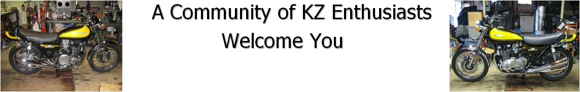
The black plastic disk is retained to the upper cup by two steel tabs swaged into depressions in the disk. The tabs can be formed away from their depressions in the disk, using gentle persuasion and a small flat blade screwdriver. A steel standoff leg is wrapped around the sw. wire harness, and must be unwrapped prior to separating the disk from the cup. Then, holding the sw. assy. upside-down (disk up), the disk can be removed from the upper cup. Nothing comes springing out, but the rotary contact components will fall out if the disk is down when removed.
The upper cup appears below, upper left. Stationary contact disk upper right, and rotary contact components appear lower right. Three contact points are on each of two, interchangeable rotary contacts. The contact at 8 o'clock is in it's normal assembled position. The other parts (lower right) are the individual components of the rotary contact at the 2 o'clock position. The red tube is used only to hold the contact upright for the pic. A steel ball can just be seen in the hole of the rotor. This is for the positive detents at each position of the rotor. The spring holds the rotary contact firmly against stationary terminal disc, and the ball in the detents. The brown rectangular fiber insert goes between the spring and the three-point rotary contact, insulating the contact from the rest of the bike. (This is NOT the problem switch. It's a spare that we were willing to disassemble/sacrifice if needed as a learning tool.)
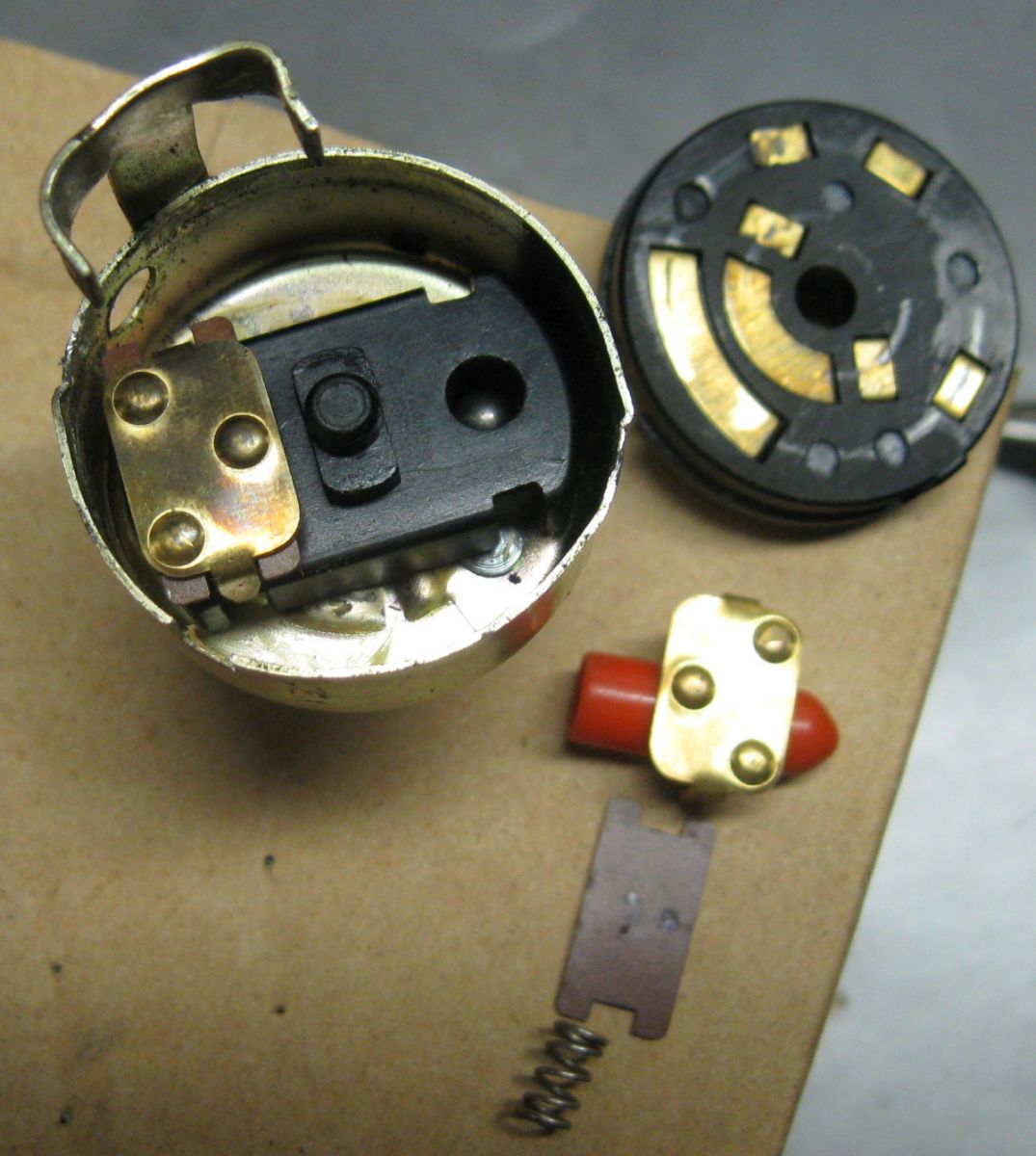
The pic below shows the stationary contacts of the problem switch. The dried old lube that had been applied at the factory has been cleaned using a degreasing solvent. Of particular interest here is the contact at 3 o'clock. This is the contact for the WHITE circuit. Note the depression that has been eroded in the contact. This is half the problem. At disassembly, this depression was coated with old grease that had carbonized and baked onto it. Physical burnishing was required to renew the contact surface.
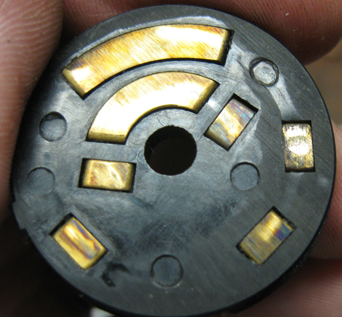
The pic below shows the rotary contact of the problem switch that switches the white wire circuit, among others. Note the flat worn on the contact point at the bottom left. This is the contact point that opens/closes the WHITE circuit. This flat is the other half of the problem. It too had old, carbonized grease baked onto it. It's been burnished as seen in this pic. Note the discoloration of the area surrounding the worn contact point, likely from heat.
Resolution: after cleaning everything and burnishing the damaged contacts, we swapped the positions of the two movable contacts. Doing so placed a relatively fresh contact point in the WHITE circuit. A dab of conductive grease on all the stationary contacts ensures smooth operation and good electrical conductivity.
An additional issue was identified while the switch was disassembled: the ignition sw. wires are soldered to lugs of the stationary contacts on the outside of the disk. Under magnification we noted that the WHITE solder joint appeared “cold” and incomplete. A tiny dab of flux and a small drop of fresh solder fixed it right up. The cold joint was too small to get a good pic. In this particular case, the cold solder joint probably contributed to the damage seen on the WHITE circuit contacts by generating excess heat.
Reassembly in reverse order, gently tap the steel tabs into the depressions of the disk, and we're done.
Those familiar with Z-1 electrics know the WHITE circuit carries upwards of 15 amps. The sizing of the contact points for the WHITE circuit in the ignition sw. is barely adequate for this much current. This switch design is why excess resistance is often observed at the ignition sw. WHITE circuit, manifesting as voltage drop. It is this reduction in voltage that leads to poor spark, and is why the coil relay mod restores full voltage to the coils, by bypassing the WHITE ignition sw. contacts for coil power and using much more robust relay contacts.
In hindsight, we should have measured the resistance across the WHITE circuit contacts with the sw. in the ON position prior to disassembly, and compared that to the repaired resistance. Too, we'll be doing the coil relay mod this winter once we've obtained the necessary bullet connectors.
Hope this helps someone salvage an otherwise suspect OEM ignition sw.
Good Ridin'
slmjim & Z1BEBE
An intermittent electrical problem drove us to explore the inside workings of a Z-1 ignition switch. This is what we found:
Bike: recently restored '72 Z-1. 192 mi.
Symptom: Happened three times over about 15 starts. Bike would crank & start normally. When the lights were switched ON after starting, the entire electrical system would go dead. Cycling the ignition sw. OFF /ON restored normal power in each case, and the bike could then be ridden. Further testing by slowly rotating and rocking the ignition sw. repeatedly through ON/OFF cycles revealed instantaneous, intermittent opens, as indicated by flickering oil/neutral lights. This led us to strongly suspect the ignition switch itself as the culprit.
Because we had been able to match the OEM key #'s on the set of ignition, seat and fork locks, we wanted to salvage the ignition sw. if at all possible.
The ignition sw. consists of three basic sub-assemblies:
1) the key cylinder,
2) the steel upper “cup” assembly, containing the rotor and rotary contacts moved by the key cylinder. The key cylinder appears to be permanently attached to the cup assy. We did not attempt to separate the key cylinder from the cup assy.
3) the black plastic lower assembly (stationary terminal disc), to which the wires are soldered to the outside lugs of the brass stationary contacts. The flat stationary contacts are on the reverse side from the wires, and are where the rotary contacts open/close the various circuits depending on the position of the rotor.
The black plastic disk is retained to the upper cup by two steel tabs swaged into depressions in the disk. The tabs can be formed away from their depressions in the disk, using gentle persuasion and a small flat blade screwdriver. A steel standoff leg is wrapped around the sw. wire harness, and must be unwrapped prior to separating the disk from the cup. Then, holding the sw. assy. upside-down (disk up), the disk can be removed from the upper cup. Nothing comes springing out, but the rotary contact components will fall out if the disk is down when removed.
The upper cup appears below, upper left. Stationary contact disk upper right, and rotary contact components appear lower right. Three contact points are on each of two, interchangeable rotary contacts. The contact at 8 o'clock is in it's normal assembled position. The other parts (lower right) are the individual components of the rotary contact at the 2 o'clock position. The red tube is used only to hold the contact upright for the pic. A steel ball can just be seen in the hole of the rotor. This is for the positive detents at each position of the rotor. The spring holds the rotary contact firmly against stationary terminal disc, and the ball in the detents. The brown rectangular fiber insert goes between the spring and the three-point rotary contact, insulating the contact from the rest of the bike. (This is NOT the problem switch. It's a spare that we were willing to disassemble/sacrifice if needed as a learning tool.)
The pic below shows the stationary contacts of the problem switch. The dried old lube that had been applied at the factory has been cleaned using a degreasing solvent. Of particular interest here is the contact at 3 o'clock. This is the contact for the WHITE circuit. Note the depression that has been eroded in the contact. This is half the problem. At disassembly, this depression was coated with old grease that had carbonized and baked onto it. Physical burnishing was required to renew the contact surface.
The pic below shows the rotary contact of the problem switch that switches the white wire circuit, among others. Note the flat worn on the contact point at the bottom left. This is the contact point that opens/closes the WHITE circuit. This flat is the other half of the problem. It too had old, carbonized grease baked onto it. It's been burnished as seen in this pic. Note the discoloration of the area surrounding the worn contact point, likely from heat.
Resolution: after cleaning everything and burnishing the damaged contacts, we swapped the positions of the two movable contacts. Doing so placed a relatively fresh contact point in the WHITE circuit. A dab of conductive grease on all the stationary contacts ensures smooth operation and good electrical conductivity.
An additional issue was identified while the switch was disassembled: the ignition sw. wires are soldered to lugs of the stationary contacts on the outside of the disk. Under magnification we noted that the WHITE solder joint appeared “cold” and incomplete. A tiny dab of flux and a small drop of fresh solder fixed it right up. The cold joint was too small to get a good pic. In this particular case, the cold solder joint probably contributed to the damage seen on the WHITE circuit contacts by generating excess heat.
Reassembly in reverse order, gently tap the steel tabs into the depressions of the disk, and we're done.
Those familiar with Z-1 electrics know the WHITE circuit carries upwards of 15 amps. The sizing of the contact points for the WHITE circuit in the ignition sw. is barely adequate for this much current. This switch design is why excess resistance is often observed at the ignition sw. WHITE circuit, manifesting as voltage drop. It is this reduction in voltage that leads to poor spark, and is why the coil relay mod restores full voltage to the coils, by bypassing the WHITE ignition sw. contacts for coil power and using much more robust relay contacts.
In hindsight, we should have measured the resistance across the WHITE circuit contacts with the sw. in the ON position prior to disassembly, and compared that to the repaired resistance. Too, we'll be doing the coil relay mod this winter once we've obtained the necessary bullet connectors.
Hope this helps someone salvage an otherwise suspect OEM ignition sw.
Good Ridin'
slmjim & Z1BEBE
A biker looks at your engine and chrome.
A Rider looks at your odometer and tags.
1973 ('72 builds) Z1 x2
1974 Z1-A x2
1975 Z1-B x2
1993 CB 750 Nighthawk x2
2009 ST1300A
www.kawasaki-z-classik.com
A Forum tightly focused on all things Z1 and Z2.
A Rider looks at your odometer and tags.
1973 ('72 builds) Z1 x2
1974 Z1-A x2
1975 Z1-B x2
1993 CB 750 Nighthawk x2
2009 ST1300A
www.kawasaki-z-classik.com
A Forum tightly focused on all things Z1 and Z2.
Last edit: 26 Aug 2017 07:30 by slmjim+Z1BEBE. Reason: Corrections
The following user(s) said Thank You: JR, martin_csr, Gdailey2112, howardhb
Please Log in or Create an account to join the conversation.
- RonKZ650
-
- Offline
- User
-
Registered
- Posts: 3715
- Thanks: 251
Re: Z-1 ignition switch innards and troubleshooting
26 Aug 2017 05:35
Good write up. Yes the switches go bad in basically the same scenerio as the burnt fuse problems many encounter. The copper contacts get corroded after years of time have passed, cause a less secure contact, then heat and burn. Sometimes wires even completely come unsoldered from the switch due to the heat. Luckily, as you said, the whole contact assm can be swapped in keeping the original key cylinder.
321,000 miles on KZ's that I can remember. Not going to see any more.
Please Log in or Create an account to join the conversation.
Moderators: Street Fighter LTD