Wiring help
- Buys
-
 Topic Author
- Offline
- User
-

Registered
- Posts: 23
- Thanks: 0
Re: Wiring help
31 Jan 2018 05:13
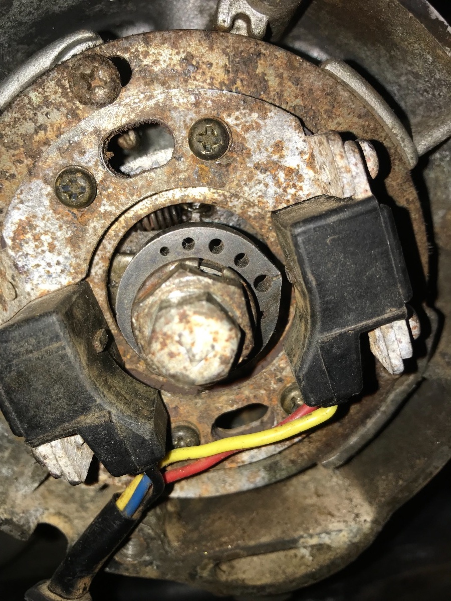
What is that lobe called? Are they easy to replace? Thank you all for your help
Please Log in or Create an account to join the conversation.
- TexasKZ
-

- Offline
- Platinum Member
-

Registered
- Posts: 8185
- Thanks: 2674
Re: Wiring help
31 Jan 2018 05:35
1982 KZ1000 LTD parts donor
1981 KZ1000 LTD awaiting resurrection
2000 ZRX1100 not ridden enough
www.kzrider.com/11-projects/620336-anoth...uild-thread?start=24
1981 KZ1000 LTD awaiting resurrection
2000 ZRX1100 not ridden enough
www.kzrider.com/11-projects/620336-anoth...uild-thread?start=24
Please Log in or Create an account to join the conversation.
- loudhvx
-
- Offline
- KZr Legend
-

Registered
- Posts: 10863
- Thanks: 1622
Re: Wiring help
31 Jan 2018 10:05 - 31 Jan 2018 10:12
Just the lobe, by itself, is not available as a separate part. It is part of the advancer assembly, as Martin mentioned. But you can remove it from the advancer boss with a decent press. It's just a mild interference fit, so it doesn't take too much force to remove it. But you should have a press to do it evenly to prevent damage.
But you really just need to get a new rotor or complete advancer assembly since you probably won't find any lobes available by themselves. If you get a deal on a broken advancer, or even maybe an advancer from a different size Kz (but I'm not sure of that), you can swap the lobe over to your advancer.
Pay very close attention to the alignment of the lobe, as that will affect/adjust the timing. Also note that the lobe is not symmetrical, so make sure to get the orientation correct.
If you can take the timing plate off and post more photos of the lobe, we can see if the tip is really damaged or if it's just a strange photo.
Also, if the tip is damaged, why is it damaged? It can get damaged if the tip collides with the pickups, but there would be metal filings all over the magnets. And you want to make sure the crank is not wobbling (bent). You can check that by turning the crank and see if there's any runout. That is highly unlikely, but I can't figure why else the lobe would be so worn down.
1981 KZ550 D1 gpz.
Kz550 valve train warning.
Other links.
Kz550 valve train warning.
Other links.
Last edit: 31 Jan 2018 10:12 by loudhvx.
Please Log in or Create an account to join the conversation.
- Buys
-
Topic Author
- Offline
- User
-
Registered
- Posts: 23
- Thanks: 0
Re: Wiring help
04 Feb 2018 18:40
So I got a new advancer assembly and just removed the lobe itself and put that in and I still don’t have spark. The ohms from each of the pickup coil is about 420 ohms and the GAp between the lobe and the pickup is about .042 inches. Is that to much for spark?
Please Log in or Create an account to join the conversation.
- loudhvx
-
- Offline
- KZr Legend
-
Registered
- Posts: 10863
- Thanks: 1622
Re: Wiring help
04 Feb 2018 20:29 - 04 Feb 2018 20:31
You can check for spark by tapping the center pole of the pickup with a steel screwdriver tip. If it sparks that way then maybe the gap is too big, but that seems doubtful.
Have you had the timing plate apart? If so it can be assembled wrong then might not spark.
gpzweb.s3-website-us-east-1.amazonaws.co.../PickupAndRotor.html
Do you have an update on how you have things wired exactly?
Have you had the timing plate apart? If so it can be assembled wrong then might not spark.
gpzweb.s3-website-us-east-1.amazonaws.co.../PickupAndRotor.html
Do you have an update on how you have things wired exactly?
1981 KZ550 D1 gpz.
Kz550 valve train warning.
Other links.
Kz550 valve train warning.
Other links.
Last edit: 04 Feb 2018 20:31 by loudhvx.
Please Log in or Create an account to join the conversation.
- Buys
-
Topic Author
- Offline
- User
-
Registered
- Posts: 23
- Thanks: 0
Re: Wiring help
05 Feb 2018 05:30
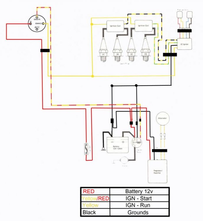
I’ll try the screw driver thing. I am 100% sure that the timing plate is on correct. With the wires on the bottom and the magnets behind the plate. I will draw a wiring diagram for you guys to explain jt easier
Please Log in or Create an account to join the conversation.
- loudhvx
-
- Offline
- KZr Legend
-
Registered
- Posts: 10863
- Thanks: 1622
Re: Wiring help
05 Feb 2018 14:35That's good, but the critical thing is which way the magnets are facing. They can easily go either way. The wrong way will weaken the pickup signal.Buys wrote: ... I am 100% sure that the timing plate is on correct. With the wires on the bottom and the magnets behind the plate. I will draw a wiring diagram for you guys to explain jt easier
1981 KZ550 D1 gpz.
Kz550 valve train warning.
Other links.
Kz550 valve train warning.
Other links.
Please Log in or Create an account to join the conversation.
- Buys
-
Topic Author
- Offline
- User
-
Registered
- Posts: 23
- Thanks: 0
Re: Wiring help
05 Feb 2018 16:04
I’ll send a pic of the magnets when I get a chance. Thank yoh
Please Log in or Create an account to join the conversation.
- loudhvx
-
- Offline
- KZr Legend
-
Registered
- Posts: 10863
- Thanks: 1622
Re: Wiring help
05 Feb 2018 19:07
A picture will not tell me (or anyone) which pole, North or South, is facing upward. Read that link on how to get the magnet polarity correct. That will also help determine if you are getting a signal using a voltmeter.
1981 KZ550 D1 gpz.
Kz550 valve train warning.
Other links.
Kz550 valve train warning.
Other links.
Please Log in or Create an account to join the conversation.
- Buys
-
Topic Author
- Offline
- User
-
Registered
- Posts: 23
- Thanks: 0
Re: Wiring help
05 Feb 2018 19:28
I found how to to check to make sure the magnets are correct and I will do that tomrrow. My wiring diagram is this but the brown wire( from the voltage regulator) is connected to power like you guys told me earlier on this thread
Please Log in or Create an account to join the conversation.
- Buys
-
Topic Author
- Offline
- User
-
Registered
- Posts: 23
- Thanks: 0
Re: Wiring help
05 Feb 2018 19:30
Also for the ignition switch I have one switch killing the power to the coils and the ignition button connected to the solenoid and the batteryb
Please Log in or Create an account to join the conversation.
- loudhvx
-
- Offline
- KZr Legend
-
Registered
- Posts: 10863
- Thanks: 1622
Re: Wiring help
06 Feb 2018 00:07 - 06 Feb 2018 00:12
If that diagram truly represents how you have the ignition wired, it will not work that way. See earlier discussion about wire colors on the igniter.
Black/yellow is ground.
Black is for 1-4 coil.
Green is for 2-3 coil.
There should be no green/yellow wire.
The description is too ambiguous to tell how you have it wired,
Black/yellow is ground.
Black is for 1-4 coil.
Green is for 2-3 coil.
There should be no green/yellow wire.
Do you mean the starter button?Buys wrote: Also for the ignition switch I have one switch killing the power to the coils and the ignition button connected to the solenoid and the batteryb
The description is too ambiguous to tell how you have it wired,
1981 KZ550 D1 gpz.
Kz550 valve train warning.
Other links.
Kz550 valve train warning.
Other links.
Last edit: 06 Feb 2018 00:12 by loudhvx.
Please Log in or Create an account to join the conversation.
Moderators: Street Fighter LTD