Connecting Rod Orientation.
- SU8ZERO
-
 Topic Author
- Offline
- User
-

Registered
- Posts: 4
- Thanks: 0
Connecting Rod Orientation.
16 Aug 2020 13:22
So i disassembled my KZ400D engine, trying to find a smoking gun to a tapping noise i was hearing(learned now that apparently KZ are just noisy motors at idle).
Anyways I took almost everything apart in the engine, I know which connecting rod is which, and i know the con rod cap orientation. I cannot remember or find out which way the rod should be orientated on the crankshaft, there is a small visible difference between the sides. If anyone has any insight or possibly pictures from an engine overhaul, that would be very helpful.
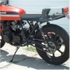
Note the small point inside the red circle.
Anyways I took almost everything apart in the engine, I know which connecting rod is which, and i know the con rod cap orientation. I cannot remember or find out which way the rod should be orientated on the crankshaft, there is a small visible difference between the sides. If anyone has any insight or possibly pictures from an engine overhaul, that would be very helpful.
Note the small point inside the red circle.
1977 KZ400D
1970 TS250-II
1970 TS250-II
Attachments:
Please Log in or Create an account to join the conversation.
- loudhvx
-
- Offline
- KZr Legend
-

Registered
- Posts: 10864
- Thanks: 1619
Re: Connecting Rod Orientation.
17 Aug 2020 06:53 - 17 Aug 2020 07:00
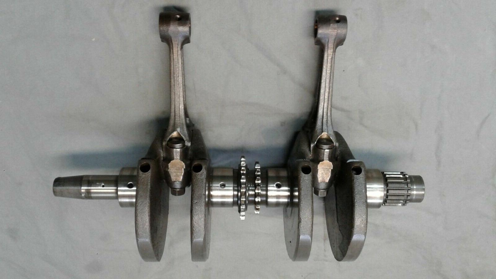
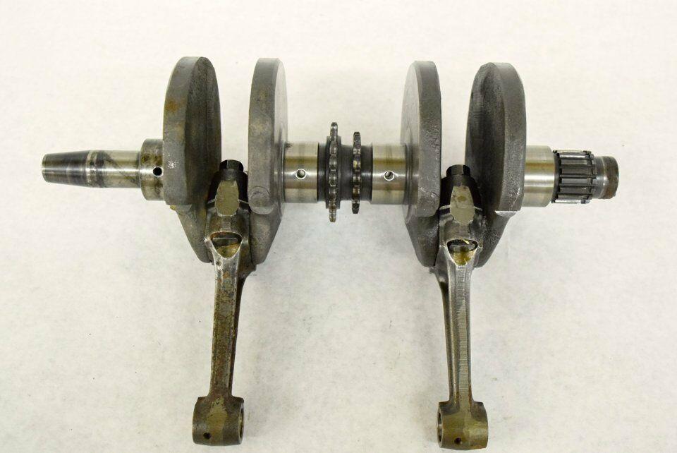
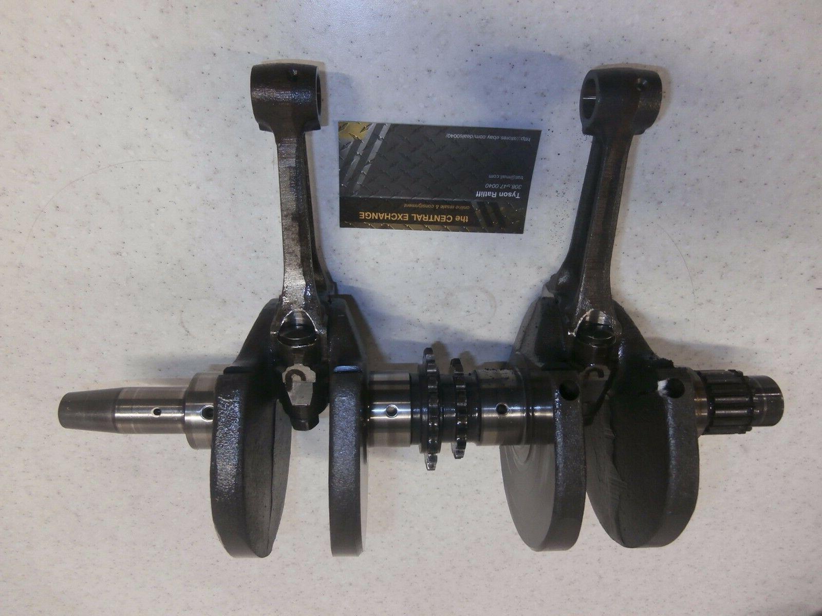
I only have a few photos from the internet. Maybe you can see some detail that would help.
Unfortunately, who knows if the rods are installed correctly in these photos. These are mostly from people selling parts.
That little casting mark doesn't show up in the photos of an assembled crank.
Are there two sets of oil holes on the wrist-pin end of the rod? If not, then the crank photos below conflict with each other. The first photo and the last photo are actually of the same example crank. The other two are different cranks.
1981 KZ550 D1 gpz.
Kz550 valve train warning.
Other links.
Kz550 valve train warning.
Other links.
Last edit: 17 Aug 2020 07:00 by loudhvx.
The following user(s) said Thank You: SU8ZERO
Please Log in or Create an account to join the conversation.
- SU8ZERO
-
Topic Author
- Offline
- User
-
Registered
- Posts: 4
- Thanks: 0
Re: Connecting Rod Orientation.
17 Aug 2020 16:47
HAHA! you are doing the exact same thing im doing. Ive emailed probably 4 people on ebay who are selling crankshafts with connecting rods attached. Unfortunately the wrist pin oil holes do not help, there is a hole on each side of the wrist pin.
So far ive only gotten one reply on ebay, and it contradicts another photo i found of connecting rods on a crankshaft. Thank you for the response @loudhvx
So far ive only gotten one reply on ebay, and it contradicts another photo i found of connecting rods on a crankshaft. Thank you for the response @loudhvx
1977 KZ400D
1970 TS250-II
1970 TS250-II
Please Log in or Create an account to join the conversation.
- SU8ZERO
-
Topic Author
- Offline
- User
-
Registered
- Posts: 4
- Thanks: 0
Re: Connecting Rod Orientation.
17 Aug 2020 16:57
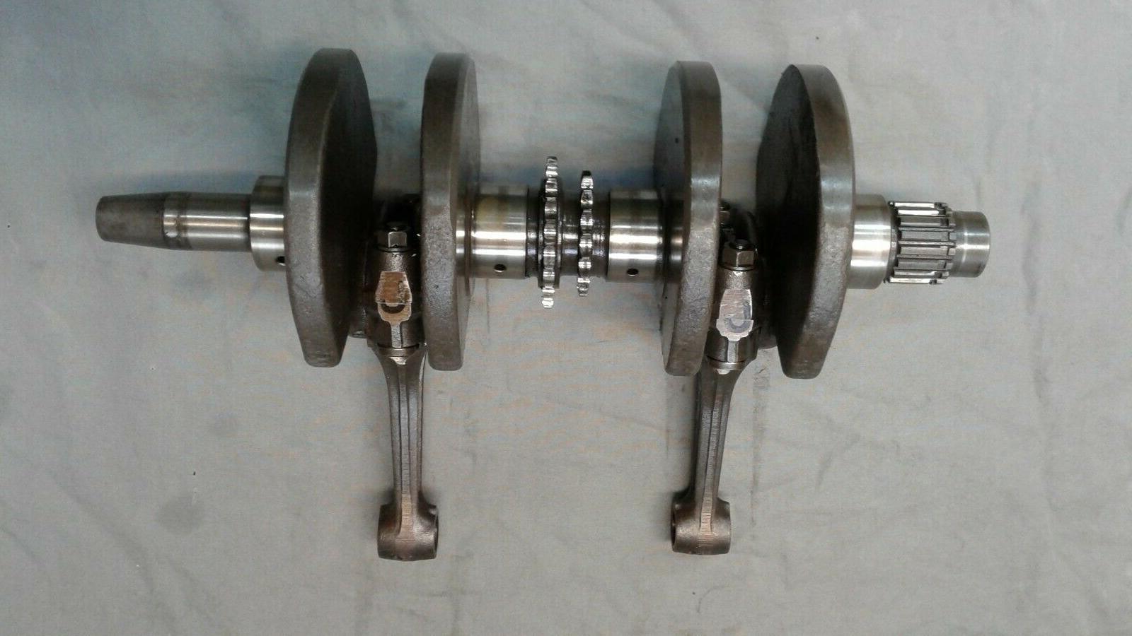
Ya thats what ive been doing, messaging people selling the crankshaft with connecting rods on ebay. So far only one response, and unfortunately that photo contradicts another I found. This is the best photo ive gotten so far.
Also, yes the wrist pins have 2 holes each
Thanks for the response
Also, yes the wrist pins have 2 holes each
Thanks for the response
1977 KZ400D
1970 TS250-II
1970 TS250-II
Please Log in or Create an account to join the conversation.
- Nebr_Rex
-

- Offline
- User
-
Registered
- Posts: 1888
- Thanks: 295
Re: Connecting Rod Orientation.
17 Aug 2020 19:30
1] The rod caps are oriented so the tangs on the bearing inserts are mated to each other.
2] The chamfer on each side of the big end of the rod is the same. They can be installed either way.
3] Almost all of the 'load' on the bearings is in the center of the upper bearing shell.
Just install them both the same way.
2] The chamfer on each side of the big end of the rod is the same. They can be installed either way.
3] Almost all of the 'load' on the bearings is in the center of the upper bearing shell.
Just install them both the same way.
2002 ZRX1200R
81 GPz1100
79 KZ1000st daily ride
79 KZ1000mk2 prodject
78 KZ650sr
78 KZ650b
81 KZ750e
80 KZ750ltd
77 KZ400/440 cafe project
76 KZ400/440 Fuel Injected
www.dotheton.com/forum/index.php?topic=39120.0
.
81 GPz1100
79 KZ1000st daily ride
79 KZ1000mk2 prodject
78 KZ650sr
78 KZ650b
81 KZ750e
80 KZ750ltd
77 KZ400/440 cafe project
76 KZ400/440 Fuel Injected
www.dotheton.com/forum/index.php?topic=39120.0
.
The following user(s) said Thank You: loudhvx, SU8ZERO
Please Log in or Create an account to join the conversation.
- SU8ZERO
-
Topic Author
- Offline
- User
-
Registered
- Posts: 4
- Thanks: 0
Re: Connecting Rod Orientation.
18 Aug 2020 05:44
Thanks for the input. Really kicking myself for not marking the direction of the rods even though i marked everything else. First engine teardown ive done by myself.
1977 KZ400D
1970 TS250-II
1970 TS250-II
Please Log in or Create an account to join the conversation.
Moderators: Street Fighter LTD