electrical gurus (Lou?) got a challenge
- loudhvx
-
- Offline
- KZr Legend
-

Registered
- Posts: 10863
- Thanks: 1622
Re: electrical gurus (Lou?) got a challenge (N2O)
16 May 2007 14:13
77KZ650 wrote:
He is using a timing circuit to prevent the ECU from shutting down. I want to use a timing circuit to prevent backfires when you let up on the button, but maybe it's not necessary.
Earlier, it was thought the resistor was to be in series with the temp sensor, but he is saying the temp sensor is removed from the circuit during N2O use. This is a big difference.
Can the sensor be used in addition to the resistor, or must it be replaced by the resistor, and why?
I suspect the sensor could be left in the circuit (as we were assuming), but we need to know if the resistance must go up or down during N2O use.
I'll post what I have so far.

D1 is to prevent arcing caused by the solenoid so the start-button contacts won't burn.
D2 is to isolate the relay in order to use C1 as a time delay on the temp sensor. This is to provide a split second of extra fuel while the fog in the airbox clears out. D2 and C1 may not be necessary, though. I'm not familiar with N2O injection, just circuits")
Post edited by: loudhvx, at: 2007/05/22 02:26
So you can switch it on the fly, it uses a small timer to connect the resistor first and then the timer kills the normal circuit after the first circuit has already been connected, this way the wire is never actually broken, it has around a 0.1 second delay, then another little box that has a tiny relay and capacitors so it does the opposite when off the button, the capacitors takes about .3 of a second to drain which then stops the relay taking it back to stock temp sensor.
He is using a timing circuit to prevent the ECU from shutting down. I want to use a timing circuit to prevent backfires when you let up on the button, but maybe it's not necessary.
Earlier, it was thought the resistor was to be in series with the temp sensor, but he is saying the temp sensor is removed from the circuit during N2O use. This is a big difference.
Can the sensor be used in addition to the resistor, or must it be replaced by the resistor, and why?
I suspect the sensor could be left in the circuit (as we were assuming), but we need to know if the resistance must go up or down during N2O use.
I'll post what I have so far.
D1 is to prevent arcing caused by the solenoid so the start-button contacts won't burn.
D2 is to isolate the relay in order to use C1 as a time delay on the temp sensor. This is to provide a split second of extra fuel while the fog in the airbox clears out. D2 and C1 may not be necessary, though. I'm not familiar with N2O injection, just circuits
Post edited by: loudhvx, at: 2007/05/22 02:26
1981 KZ550 D1 gpz.
Kz550 valve train warning.
Other links.
Kz550 valve train warning.
Other links.
Please Log in or Create an account to join the conversation.
- 77KZ650
-
 Topic Author
- Offline
- User
-

Registered
- Posts: 1397
- Thanks: 7
Re: electrical gurus (Lou?) got a challenge (N2O)
16 May 2007 16:14
maybe he worded it wrong, it doesnt replace the temp sensor with a resistor, it adds resistance to the circuit. if it was replaced, it would only be working correctly for 1 operating temp, and the temp definatly varies:P
as a side note I know that another guy uses a crude setup to run a lot of spray. it adds the resistor to the circuit, but it only works well when hes on the juice, when hes not spraying it runs very rich. he has to shut the bike off, plug it in then drive with a rich setup till he shuts down and takes it out. running a rich map is bad for HP when you arent spraying though:pinch:
as a side note I know that another guy uses a crude setup to run a lot of spray. it adds the resistor to the circuit, but it only works well when hes on the juice, when hes not spraying it runs very rich. he has to shut the bike off, plug it in then drive with a rich setup till he shuts down and takes it out. running a rich map is bad for HP when you arent spraying though:pinch:
07 MDP Rookie of the Year
01 ZX-12R street/drag bike. 8.97 @155.7 pump gas, dot tires, no bars, no power adders. top speed in the 1/4: 161MPH
01 ZX-12R street/drag bike. 8.97 @155.7 pump gas, dot tires, no bars, no power adders. top speed in the 1/4: 161MPH
Please Log in or Create an account to join the conversation.
- loudhvx
-
- Offline
- KZr Legend
-
Registered
- Posts: 10863
- Thanks: 1622
Re: electrical gurus (Lou?) got a challenge (N2O)
16 May 2007 16:47
By his decription, "then the timer kills the normal circuit", I believe he means the temp sensor is out of the circuit. If it were not out of the circuit, he wouldn't need the timer etc. He would simply open the circuit and the resistor would come into the circuit like in the earlier diagram (albeit in a relay instead of a manual switch):

The temp sensor wouldn't be needed during N2O usage because he is setting the resistor by trial and error with a mixture detector of some sort.
If he did in fact, word it wrong, I'm not sure what he would be describing, then.
Post edited by: loudhvx, at: 2007/05/16 19:53
The temp sensor wouldn't be needed during N2O usage because he is setting the resistor by trial and error with a mixture detector of some sort.
If he did in fact, word it wrong, I'm not sure what he would be describing, then.
Post edited by: loudhvx, at: 2007/05/16 19:53
1981 KZ550 D1 gpz.
Kz550 valve train warning.
Other links.
Kz550 valve train warning.
Other links.
Please Log in or Create an account to join the conversation.
- loudhvx
-
- Offline
- KZr Legend
-
Registered
- Posts: 10863
- Thanks: 1622
Re: electrical gurus (Lou?) got a challenge (N2O)
16 May 2007 16:59
Also, can you describe the microswitch setup for WOT? Electrically, that is. Perhaps it can be used with a holding circuit so you don't have to hold the button. The button would trigger it, then the N2O would shut off automatically when you start to close the throttle. I know if I was on the juice, I'd like to be able to hold the bars without having to hold down a button with my thumb the whole time.
1981 KZ550 D1 gpz.
Kz550 valve train warning.
Other links.
Kz550 valve train warning.
Other links.
Please Log in or Create an account to join the conversation.
- loudhvx
-
- Offline
- KZr Legend
-
Registered
- Posts: 10863
- Thanks: 1622
Re: electrical gurus (Lou?) got a challenge (N2O)
16 May 2007 17:10
We need to know which figure is correct when the N2O is on. Is it fig 1, or fig 2, (in the next post)?
If it's fig 1, then no timer is needed, when the switch is open, the resistor is in series with the sensor.
If it's fig 2, then a timer may be needed (although I could easily construct an alternative without a timer).
Hopefully it's fig 1.
Post edited by: loudhvx, at: 2007/05/16 20:12
If it's fig 1, then no timer is needed, when the switch is open, the resistor is in series with the sensor.
If it's fig 2, then a timer may be needed (although I could easily construct an alternative without a timer).
Hopefully it's fig 1.
Post edited by: loudhvx, at: 2007/05/16 20:12
1981 KZ550 D1 gpz.
Kz550 valve train warning.
Other links.
Kz550 valve train warning.
Other links.
Please Log in or Create an account to join the conversation.
- loudhvx
-
- Offline
- KZr Legend
-
Registered
- Posts: 10863
- Thanks: 1622
Re: electrical gurus (Lou?) got a challenge (N2O)
16 May 2007 17:11
.

1981 KZ550 D1 gpz.
Kz550 valve train warning.
Other links.
Kz550 valve train warning.
Other links.
Please Log in or Create an account to join the conversation.
- 77KZ650
-
Topic Author
- Offline
- User
-
Registered
- Posts: 1397
- Thanks: 7
Re: electrical gurus (Lou?) got a challenge (N2O)
16 May 2007 18:58I believe he means that the timer kills the normal (no added resistance) circuit, and replaces it with the resistor added to the temp sensor circuit. just incase we are talking about different temp sensors, the one we are adding resistance to is the coolant temp sensor, not the airbox temp sensor.By his decription, "then the timer kills the normal circuit", I believe he means the temp sensor is out of the circuit. If it were not out of the circuit, he wouldn't need the timer etc. He would simply open the circuit and the resistor would come into the circuit like in the earlier diagram
by reading his description, and by thinking about the way the nitrous works(takes a sec to fill the airbox and a sec to clear out), i believe he is using a timer for the resistor to "turn on" for basically the same reason we want a timer for it to "turn off" (to keep the proper air fuel ratio) if its instantly turned on it would richen the fuel map before the airbox was fully fogged with enough nitrous for the extra fuel. these dry kits that fog the air box "hit soft" and are not as instant as spraying directly into the intake ports. i believe it requires a timer for both on and off so its not rich turning on and not lean turning off due to the way the N2O is being sprayed.
I disagree here, (i think you were thinking about the airbox temp sensor)The temp sensor wouldn't be needed during N2O usage because he is setting the resistor by trial and error with a mixture detector of some sort.
if the bike was X temp and R resistance was used instead of the temp for N amount of nitrous, then R would only make the correct air fuel ratio if X stayed the same, and it doesnt with different driving conditions. if X doubles but the ecu doesnt know, and is only going by R it wont work properly.
however
if the bike was X temp and R resistance was added to the circuit for N amount of nitrous, then the ecu still adjusts accordingly to temp change. to keep it simple if the ecu "sees" X temp it puts out F amount of fuel, if it "sees" 2X temp it puts out a differnt value F. this way we can add the same amount of resistane and nitrous each time and it will keep the correct air fuel ratio because its still dependant on engine coolant temp. fuel metering goes up and down with temp, and with resistance added to the circuit, it still goes up and down the same amount depending on temp, "the line is just moved up the graph a bit"
crude pic drawn up while i make this post because im not the greatest at describing stuff:P :
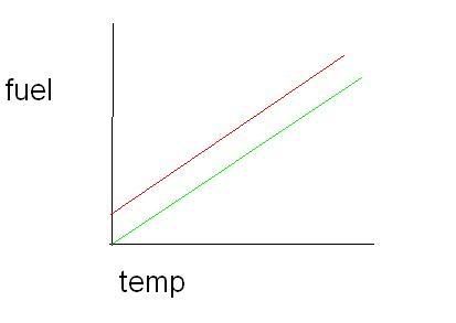
green line is normal, and red line is resistance added to circuit
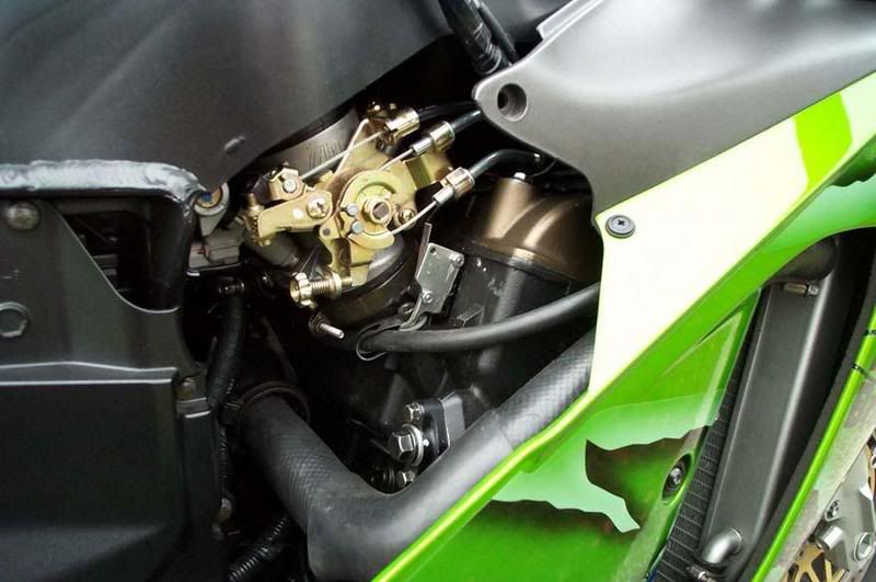
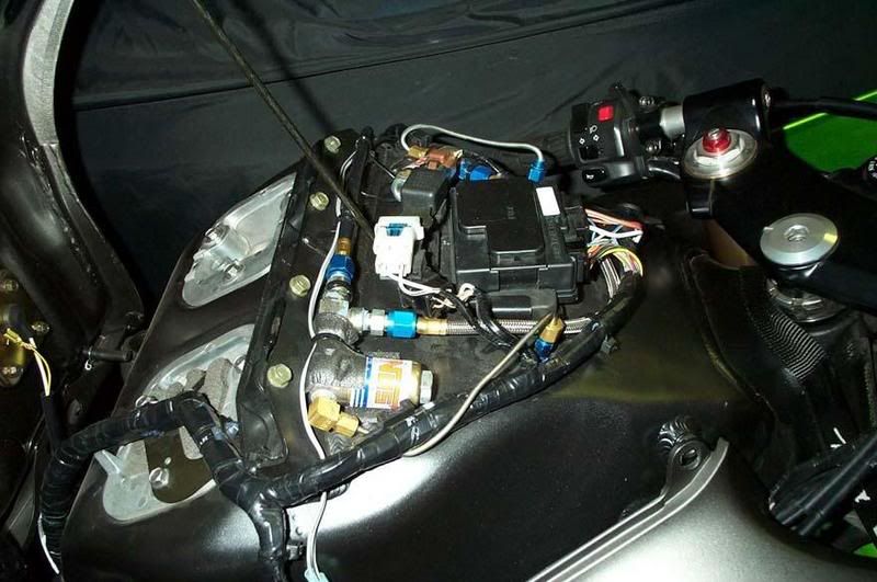
a micro switch or wide open throttle switch is simply a switch that is held in the "on" position by the throttle linkage at WOT. its the same as holding down a button. they are much better than a button because you only want to spray at WOT. my first stage will be activated with a micro switch. I want the second stage activated with a micro switch and holding down a button. if it was just a button i would risk spraying before i was WOT, and i only want to use it when i have to.
this pic shows a micro switch. note the throttle is in the closed position, and the switch is mounted on that small metal plate above the hose
definatly fig.1 only more stuff added:)
07 MDP Rookie of the Year
01 ZX-12R street/drag bike. 8.97 @155.7 pump gas, dot tires, no bars, no power adders. top speed in the 1/4: 161MPH
01 ZX-12R street/drag bike. 8.97 @155.7 pump gas, dot tires, no bars, no power adders. top speed in the 1/4: 161MPH
Please Log in or Create an account to join the conversation.
- 77KZ650
-
Topic Author
- Offline
- User
-
Registered
- Posts: 1397
- Thanks: 7
Re: electrical gurus (Lou?) got a challenge (N2O)
16 May 2007 18:59
double post
Post edited by: 77KZ650, at: 2007/05/16 22:03
Post edited by: 77KZ650, at: 2007/05/16 22:03
07 MDP Rookie of the Year
01 ZX-12R street/drag bike. 8.97 @155.7 pump gas, dot tires, no bars, no power adders. top speed in the 1/4: 161MPH
01 ZX-12R street/drag bike. 8.97 @155.7 pump gas, dot tires, no bars, no power adders. top speed in the 1/4: 161MPH
Please Log in or Create an account to join the conversation.
- loudhvx
-
- Offline
- KZr Legend
-
Registered
- Posts: 10863
- Thanks: 1622
Re: electrical gurus (Lou?) got a challenge (N2O)
16 May 2007 20:19
I agree with what you're saying, but I thought this was for drag racing only. If it's water cooled, is the temperature going to raise enough to make a difference during the 10 seconds of a race?
If it is, then yes, you'd want to use the temp sensor to adjust the fuel injection.
The thing is, though, as I read it, he implies the time delay is used in order to prevent the ECU from faulting out.
Is this someone you can contact? I'd be afraid of guessing at what he meant.
If he means the delay is to make up for the N2O lag, then we can construct a system for that.
If he means the delay is only for preventing the ECU-fault, then can we ignore the N2O lag? Is there any technical info on the system you have regarding the lag? Is there a control module of any sort for this device, or is it just a solenoid? How does the WOT switch wire in with the solenoid?
... lot of questions, I realize, but like I said, I have no experience with nitrous. I can make the circuit do what we want, but I just don't know what is required, yet.
What sort of time frame are you working with? I like designing this type of stuff, but with being the onset of summer I'm sure I'll be short on time very soon. I may be slow on replies, but I'll get to them eventually.")
If it is, then yes, you'd want to use the temp sensor to adjust the fuel injection.
The thing is, though, as I read it, he implies the time delay is used in order to prevent the ECU from faulting out.
Is this someone you can contact? I'd be afraid of guessing at what he meant.
If he means the delay is to make up for the N2O lag, then we can construct a system for that.
If he means the delay is only for preventing the ECU-fault, then can we ignore the N2O lag? Is there any technical info on the system you have regarding the lag? Is there a control module of any sort for this device, or is it just a solenoid? How does the WOT switch wire in with the solenoid?
... lot of questions, I realize, but like I said, I have no experience with nitrous. I can make the circuit do what we want, but I just don't know what is required, yet.
What sort of time frame are you working with? I like designing this type of stuff, but with being the onset of summer I'm sure I'll be short on time very soon. I may be slow on replies, but I'll get to them eventually.
1981 KZ550 D1 gpz.
Kz550 valve train warning.
Other links.
Kz550 valve train warning.
Other links.
Please Log in or Create an account to join the conversation.
- 77KZ650
-
Topic Author
- Offline
- User
-
Registered
- Posts: 1397
- Thanks: 7
Re: electrical gurus (Lou?) got a challenge (N2O)
16 May 2007 21:52
it will be mainly for drag racing(hopefully it will only be a 8-9 second race:woohoo: :evil: :whistle:  ), i really doubt ill need a second stage on the road, but it would be fun to try out every now and then on an empty road:evil: :whistle: I plan on trying some LSR if possible, and over a mile course temps are bound to change.
i can contact him, it may take some time to get a reply. hes a very busy guy. he runs a speed shop, and works looong hrs, plus hes building his bike differently this season, and that takes most of his spare time. apparently 251hp wasnt enough so hes shooting for an all out turbo setup that will be (in his words) "a nice streetable 450+ hp on pump gas":woohoo: :woohoo:
im not sure about lag from this style of spraying nitrous. i know it exists, but im not sure how "bad" it is, i think its only a couple tenths of a sec. i think its kind of like a progressive nitrous controller how it "comes on". they pulse the solenoid open rapidly staying open longer and longer till they are just open. those types of controll boxes are expensive though, and are mainly for wet kits that are sprayed into the intake ports. the reason for this is to prevent wheelspin when running a big shot. another reason for me picking a dual stage setup, its kind of progressive if i need to run a lot of spray by breaking it into 2 hits. progressive controllers are hard on solenoids since they open and close many many times during a run instead of just 2-3
what i will have is just a switch that is directly wired to the solenoid so its open or closed. nothing fancy or expensive. the only thing fancy will be the added wiring/resistor to make the second stage work well without a bunch of expensive stuff.
this is what i want: when im at WOT stage 1 kicks in automatically from the micro switch, the power commander and ecu take care of it fuel wise because they read the temp drop in the airbox. if i need stage 2 and im at WOT (the second mirco switch is allready "on") i hold the starter button down to open the other solenoid and turn on the fancy circiut i cant design:P which adds resistance to the coolant temp sensor circuit so it tricks the ecu into thinking its so many degrees different in temp so it runs a set amount richer(depending on the added resistance which i can fine tune with a wideband O2 sensor i put in the exhaust) for the extra nitrous.
time frame is probly 6 weeks give or take a week, more likely give. LOTS of time:)
), i really doubt ill need a second stage on the road, but it would be fun to try out every now and then on an empty road:evil: :whistle: I plan on trying some LSR if possible, and over a mile course temps are bound to change.i can contact him, it may take some time to get a reply. hes a very busy guy. he runs a speed shop, and works looong hrs, plus hes building his bike differently this season, and that takes most of his spare time. apparently 251hp wasnt enough so hes shooting for an all out turbo setup that will be (in his words) "a nice streetable 450+ hp on pump gas":woohoo: :woohoo:
im not sure about lag from this style of spraying nitrous. i know it exists, but im not sure how "bad" it is, i think its only a couple tenths of a sec. i think its kind of like a progressive nitrous controller how it "comes on". they pulse the solenoid open rapidly staying open longer and longer till they are just open. those types of controll boxes are expensive though, and are mainly for wet kits that are sprayed into the intake ports. the reason for this is to prevent wheelspin when running a big shot. another reason for me picking a dual stage setup, its kind of progressive if i need to run a lot of spray by breaking it into 2 hits. progressive controllers are hard on solenoids since they open and close many many times during a run instead of just 2-3
what i will have is just a switch that is directly wired to the solenoid so its open or closed. nothing fancy or expensive. the only thing fancy will be the added wiring/resistor to make the second stage work well without a bunch of expensive stuff.
this is what i want: when im at WOT stage 1 kicks in automatically from the micro switch, the power commander and ecu take care of it fuel wise because they read the temp drop in the airbox. if i need stage 2 and im at WOT (the second mirco switch is allready "on") i hold the starter button down to open the other solenoid and turn on the fancy circiut i cant design:P which adds resistance to the coolant temp sensor circuit so it tricks the ecu into thinking its so many degrees different in temp so it runs a set amount richer(depending on the added resistance which i can fine tune with a wideband O2 sensor i put in the exhaust) for the extra nitrous.
time frame is probly 6 weeks give or take a week, more likely give. LOTS of time:)
07 MDP Rookie of the Year
01 ZX-12R street/drag bike. 8.97 @155.7 pump gas, dot tires, no bars, no power adders. top speed in the 1/4: 161MPH
01 ZX-12R street/drag bike. 8.97 @155.7 pump gas, dot tires, no bars, no power adders. top speed in the 1/4: 161MPH
Please Log in or Create an account to join the conversation.
- 77KZ650
-
Topic Author
- Offline
- User
-
Registered
- Posts: 1397
- Thanks: 7
Re: electrical gurus (Lou?) got a challenge (N2O)
16 May 2007 21:53
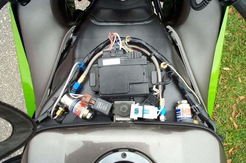
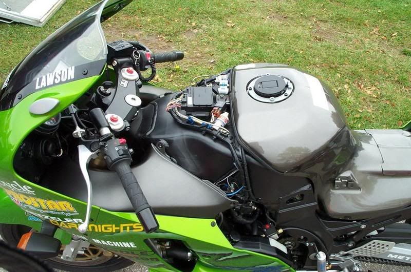
hes some pics of a nitrous setup on a 12. the frame IS the airbox:blink: ") For full size just clink the link under each one;)
For full size just clink the link under each one;)
1
2
3
Post edited by: 77KZ650, at: 2007/05/17 02:20
For full size just clink the link under each one;)
1
2
3
Post edited by: 77KZ650, at: 2007/05/17 02:20
07 MDP Rookie of the Year
01 ZX-12R street/drag bike. 8.97 @155.7 pump gas, dot tires, no bars, no power adders. top speed in the 1/4: 161MPH
01 ZX-12R street/drag bike. 8.97 @155.7 pump gas, dot tires, no bars, no power adders. top speed in the 1/4: 161MPH
Please Log in or Create an account to join the conversation.
- loudhvx
-
- Offline
- KZr Legend
-
Registered
- Posts: 10863
- Thanks: 1622
Re: electrical gurus (Lou?) got a challenge (N2O)
17 May 2007 09:49
Ok, I know this is redundant, but I just need to be sure we're on the same page (and you've probably told me this one way or another three times already, I just don't want anything blowing up in the crotch area, if you know what I mean )
We are designing the stage 2 wiring only.
Stage 2 will only be in effect while stage 1 is already spraying. (Never stage 2 by itself.)
Stage 1 and stage 2 each have their own solenoid and plumbing.
You are going to have stage 1 up and running first, before installing stage 2.
Stage 2 will come on via starter button, but you may not want it to stay on the entire time of WOT, so letting off the button will shut it down. This means any backfiring, hiccups, etc needs to be eliminated. This means a possible (or probable) need for timing the solenoid/resistor-circuit so the mixture won't go too far off in either direction (lean/rich) when the button is pushed/released.
Anytime the throttle is closed slightly, all spraying will stop.
Stage 2 will be temperature sensitive based on coolant sensor.
Stage 1 is temperature sensitive based on the airbox temp sensor.
Is that right so far?
I still have a few questions then.
First, I think it's possible to use one WOT-microswitch to do all of this, without complicating anything. Should we just plan on one microswitch, then?
Also, this is a stage 1 question, but how will the ECU know how much fuel to give for the stage 1 spray? If it's basing it on the temperature of the airbox, won't it only give enough fuel to account for cold air? That won't be enough fuel to account for the extra oxygen in the cold N2O, will it? Is the airbox temp-sensor going to get hacked as well?
Are the fuel injectors capable of handling this extra fuel flow? Does the ECU have a limit to the pulse-width it gives to the injector? If so, won't it be getting exceeded? Was the system designed, from the factory, knowing N2O might be used?
Also, is this same stage1/stage2 setup working on that ZRX in the photos, or is that something different (two solenoids and relays)?
Sorry so many questions, no rush, obviously.
)We are designing the stage 2 wiring only.
Stage 2 will only be in effect while stage 1 is already spraying. (Never stage 2 by itself.)
Stage 1 and stage 2 each have their own solenoid and plumbing.
You are going to have stage 1 up and running first, before installing stage 2.
Stage 2 will come on via starter button, but you may not want it to stay on the entire time of WOT, so letting off the button will shut it down. This means any backfiring, hiccups, etc needs to be eliminated. This means a possible (or probable) need for timing the solenoid/resistor-circuit so the mixture won't go too far off in either direction (lean/rich) when the button is pushed/released.
Anytime the throttle is closed slightly, all spraying will stop.
Stage 2 will be temperature sensitive based on coolant sensor.
Stage 1 is temperature sensitive based on the airbox temp sensor.
Is that right so far?
I still have a few questions then.
First, I think it's possible to use one WOT-microswitch to do all of this, without complicating anything. Should we just plan on one microswitch, then?
Also, this is a stage 1 question, but how will the ECU know how much fuel to give for the stage 1 spray? If it's basing it on the temperature of the airbox, won't it only give enough fuel to account for cold air? That won't be enough fuel to account for the extra oxygen in the cold N2O, will it? Is the airbox temp-sensor going to get hacked as well?
Are the fuel injectors capable of handling this extra fuel flow? Does the ECU have a limit to the pulse-width it gives to the injector? If so, won't it be getting exceeded? Was the system designed, from the factory, knowing N2O might be used?
Also, is this same stage1/stage2 setup working on that ZRX in the photos, or is that something different (two solenoids and relays)?
Sorry so many questions, no rush, obviously.
1981 KZ550 D1 gpz.
Kz550 valve train warning.
Other links.
Kz550 valve train warning.
Other links.
Please Log in or Create an account to join the conversation.
Moderators: Street Fighter LTD